
Calibrate the joints with Arduino IDE
Prepare to Enter the Calibration State
Please refer to the preparation section in the Joint Calibration.
The rationale for calibration
Understand the zero state and the coordinate system
After sending the serial command ‘c’ in the serial monitor, the robot will enter the calibration state, with all servos rotated to their zero angles, attach the head, tail, and legs prepared in the previous section to the body. They are generally perpendicular to their linked body frames.
Nybble Q's Calibration State

Install the servo-related components according to the picture above and try to ensure that they are perpendicular to each other (the upper leg is perpendicular to the torso, and the lower leg is perpendicular to the upper leg).
Note: Insert the servo-related components directly into the servo output shaft; do not turn the output shaft during this process.
Rotating the limbs counter-clockwise from their zero states will be positive (same as in polar coordinates). Viewed from the left side of the robot's body, the counter-clockwise rotation of the joint is defined as the positive direction.
Discrete angular intervals
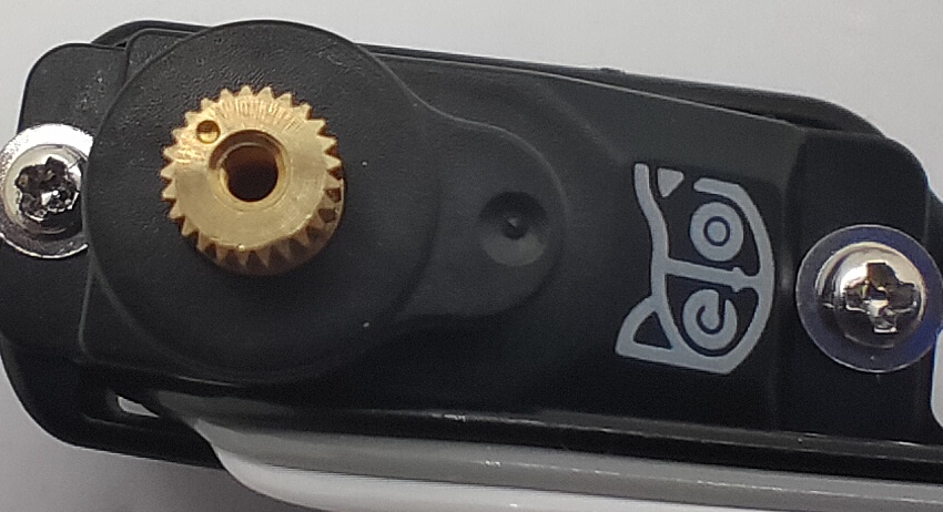
If we look closer at the servo shaft, we can see it has a certain number of teeth. That’s for attaching the servo arms and avoiding sliding in the rotational direction. In our servo sample, the gears divide 360 degrees into 25 sectors, each taking 14.4 degrees(offset of -7.2~7.2 degrees). That means we cannot always get a perfect perpendicular installation.
Calibration process
Enter the calibration state
You must double-check the position and direction of all servos.
Send the serial command ‘c’ in the serial monitor to enter the calibration state. Depending on their initial shaft direction, some may travel larger angles until stopping at the middle point. There will be noise coming from the gear system of the servos. You will see a calibration table like the following:

The first row is the joint indexes; the second row is their calibration offsets:
Index
0
1
2
3
4
5
6
7
8
9
10
11
12
13
14
15
Offset
-1
-1
-1
-1
-1
-1
-1
-1
-1
-1
-1
-1
-1
-1
-1
-1
Initial values are “-1” or “0” and should be changed by later calibration.
Attach body parts to the servos
For the installation for different product, please refer to the subpage of Joint Calibrator as above.
Fine-tune the calibration using the serial monitor
1. Joint Control Commands
The command for fine-tuning calibration (refer to the serial protocol) is formatted as cIndex Offset. Notice that there’s a space between cIndex and Offset.

For example :
c8 6This means giving the 8th servo an offset of 6 degrees.c0 -4This means giving the 0th servo(the head) an offset of -4 degrees.
The resolution of the correction amount is 1 degree; do not use decimals.
Find the best offset that can bring the limb to the zero states. It's a process of trial and error.
After calibration, remember to type ‘s’ to save the offsets. Otherwise, they will be forgotten when exiting the calibration state. You can even save every time after you’re done with one servo.
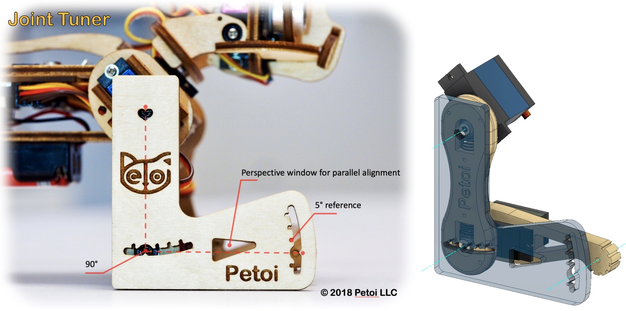
2. Use ‘L’ shaped joint tuner
When watching something, one's observations will change from different perspectives. When measuring length, one always wants to read directly above a referencing ruler.
You must keep a parallel perspective when calibrating the robot. Use the 'L'-shaped joint tuner as a parallel reference to avoid reading errors. Align the tips on the tuner with the center of the screws in the shoulder and knee joints and the little hole on the tip of the foot. Look along the co-axis of the centers. For each leg, calibrate the shoulder servos (index 8~11) first, then the knee servos(index 12~15). When calibrating the knee, use the matching triangle windows on both the tuner and shank to ensure parallel alignment.
Please use the L-shaped calibration tool included in the package as a calibration reference. According to the joint numbers shown in the picture within the calibration interface, drag the corresponding sliders or click on the blank areas of the slider tracks to fine-tune the joints to a right angle.
Please note that when calibrating the servos, adjust the upper leg first, then change the lower leg.
3. Testing and validation

After calibration, send the serial commands: ‘d’, ‘kup’, and 'kwkF' to validate the calibration. This will result in the robot symmetrically moving its limbs between the rest, stand states, and walk gait.
You may need to do a few rounds of calibrations to achieve optimal states.
4. Center of mass
Try to understand how the robot keeps balance even during walking. If you add new components to the robot, distribute its weight symmetrically about the spine. You may also need to slide the battery holder back and forth to find the best balance spot. Because the battery is heavier in the front, you can insert it in a reversed direction to shift the center of mass more toward the back.
Please do not force the robot to add heavy objects, which may cause the servos to sweep or get stuck.
Last updated