
Calibrator
The rationale for calibration
Understand the zero state and the coordinate system
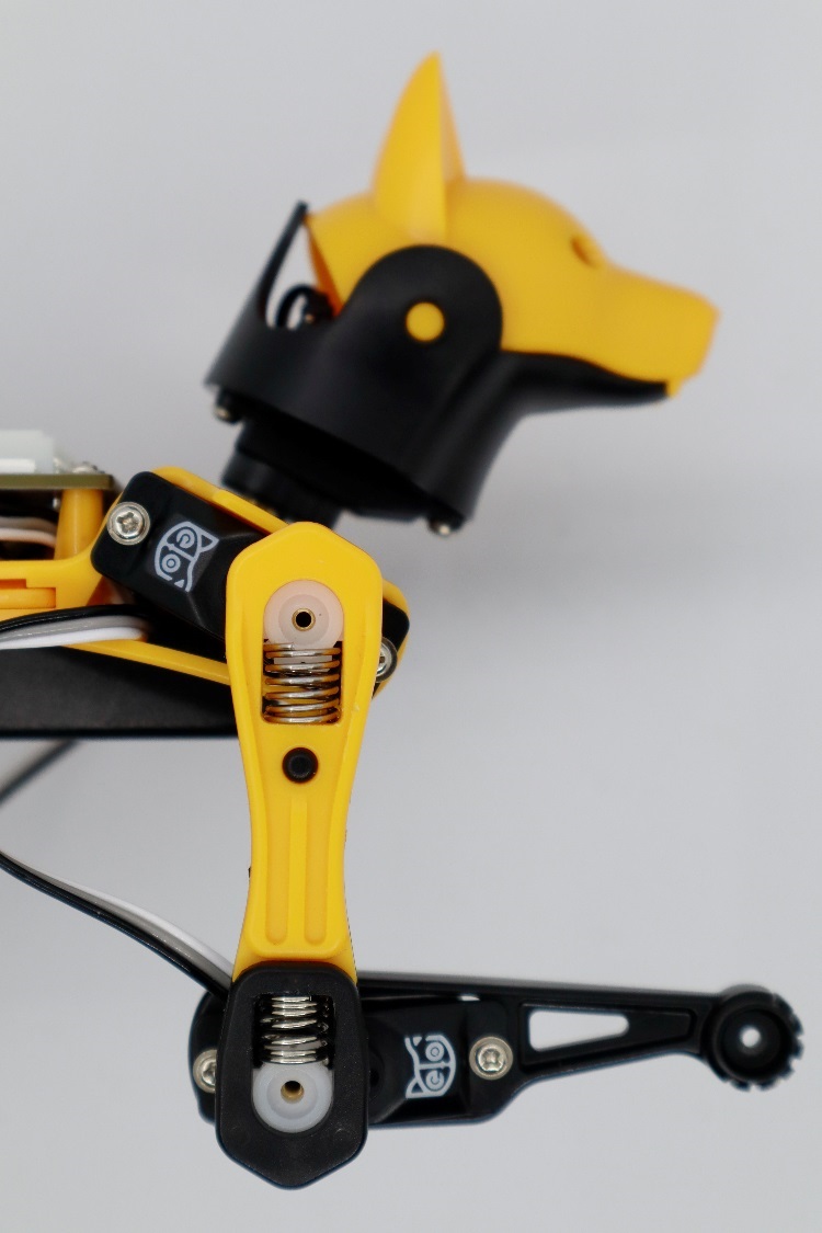
After the robot enters the calibration state, with all servos rotated to their zero angles, attach the head, tail, and legs prepared in the previous section to the body. They are generally perpendicular to their linked body frames.
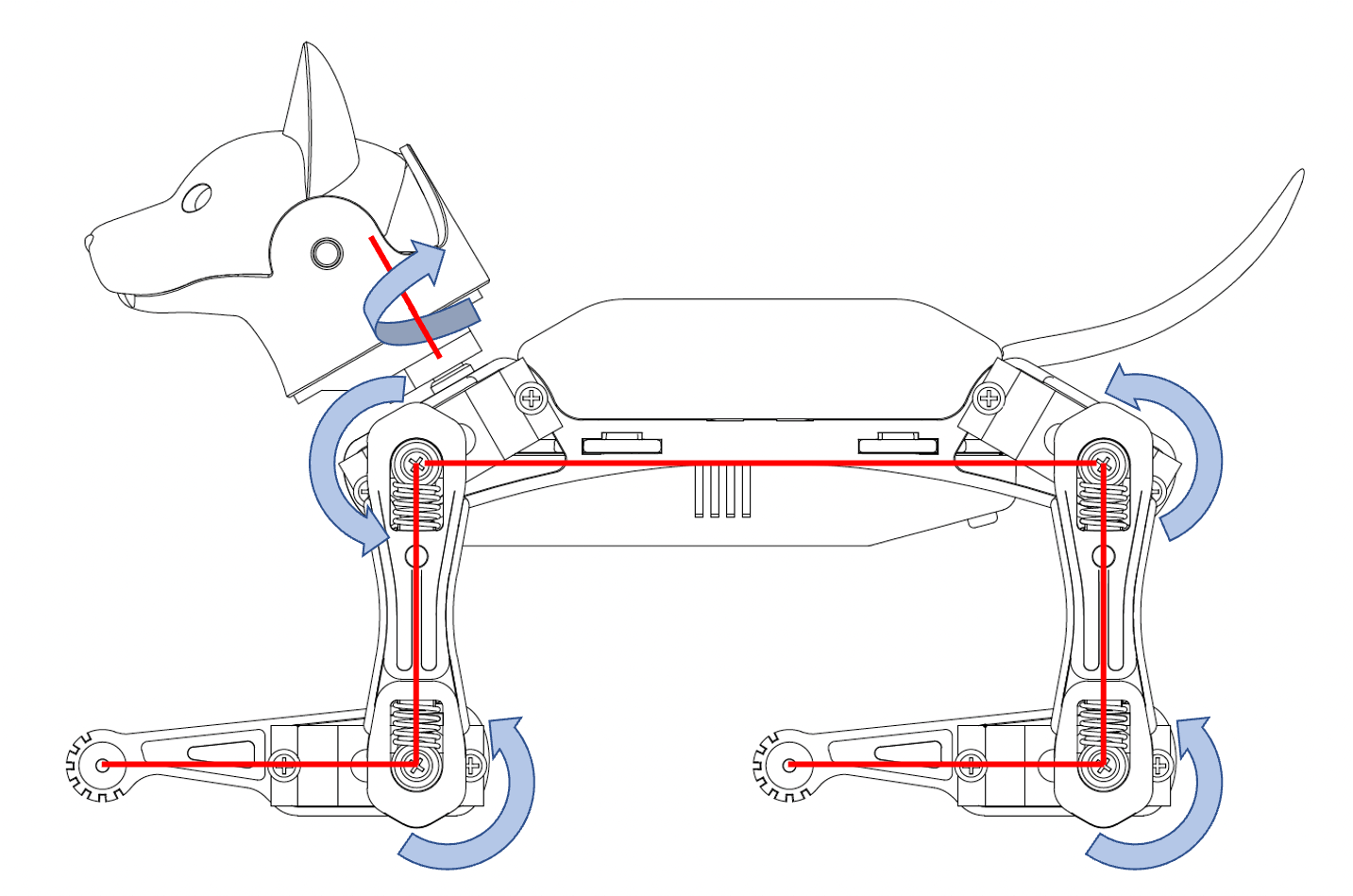
For the construction kit, please install the servo-related components as shown in the picture (calibration mode) and ensure they are perpendicular to each other (the upper leg is perpendicular to the torso, and the lower leg is perpendicular to the upper leg).
Note: Insert the servo-related components directly into the servo output shaft; do not turn the output shaft during this process.
Rotating the limbs counterclockwise from their zero states will be positive (the same as in polar coordinates). Viewed from the left side of the robot's body, the counter-clockwise rotation of the joint is defined as the positive direction.
The only exception is the head tilt angle for Nybble. It’s more natural to say head up, while it’s the result of rotating clockwise.
However, from the right side of the robot's body, the rotation directions' positive and negative are just opposite.
Discrete angular intervals
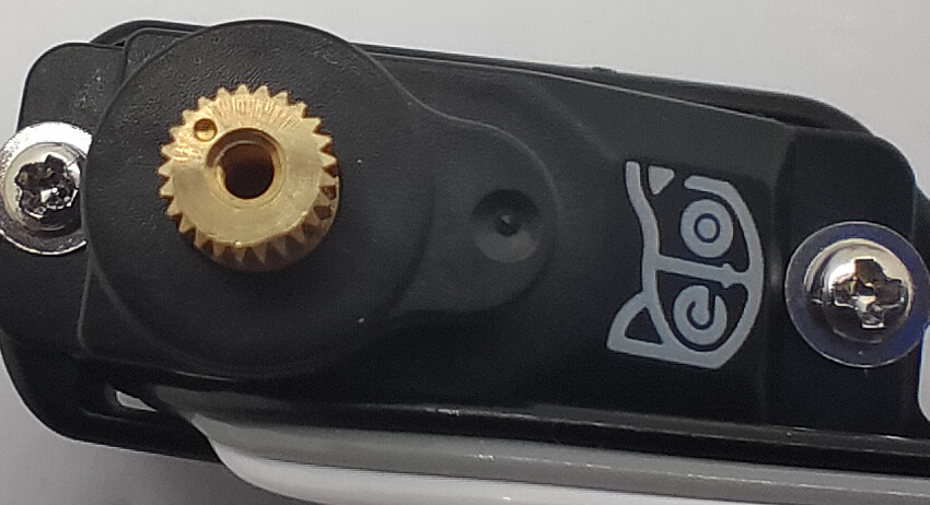
If we look closer at the servo shaft, we can see it has a certain number of teeth. That’s for attaching the servo arms and avoiding sliding in the rotational direction. In our servo sample, the gears divide 360 degrees into 25 sectors, each taking 14.4 degrees(offset of -7.2~7.2 degrees). That means we cannot always get a perfect perpendicular installation.
Calibration Interfaces
Bittle, Bittle X, and Bittle X+Arm use the same calibrator interface and process. You can ignore the mainboard type in the following pictures.
The calibrator interface for Bittle is as follows:
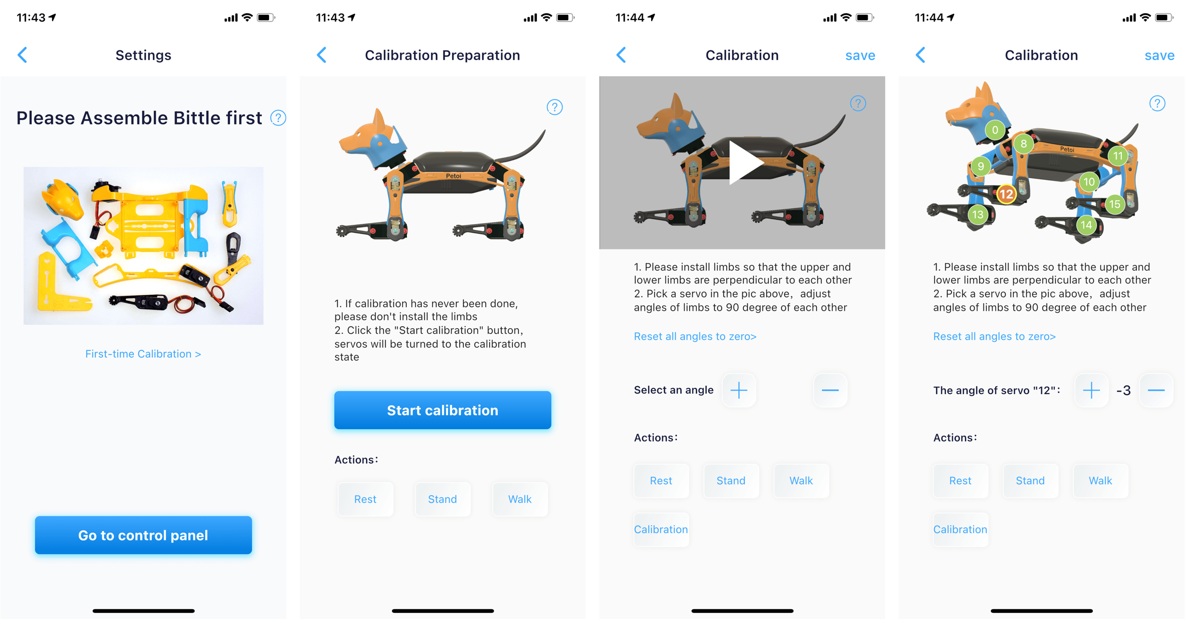
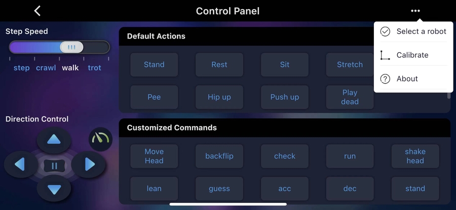
These interfaces will be displayed when you calibrate for the first time. You can also click to open the upper-right menu in the control panel and select Calibrate to re-access.
Enter the calibration state
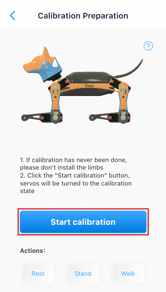
After the battery powers on the robot, follow the next steps to enter the calibration mode.
Click the Start Calibration button.
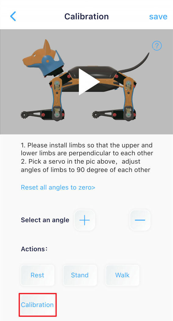
Click the Calibration button in the calibration interface.
After the robot enters the calibration mode, for the construction kit, do the following steps:
The pre-assembled robot has already had its joints calibrated, so there is no need to disassemble the joints for further calibration.
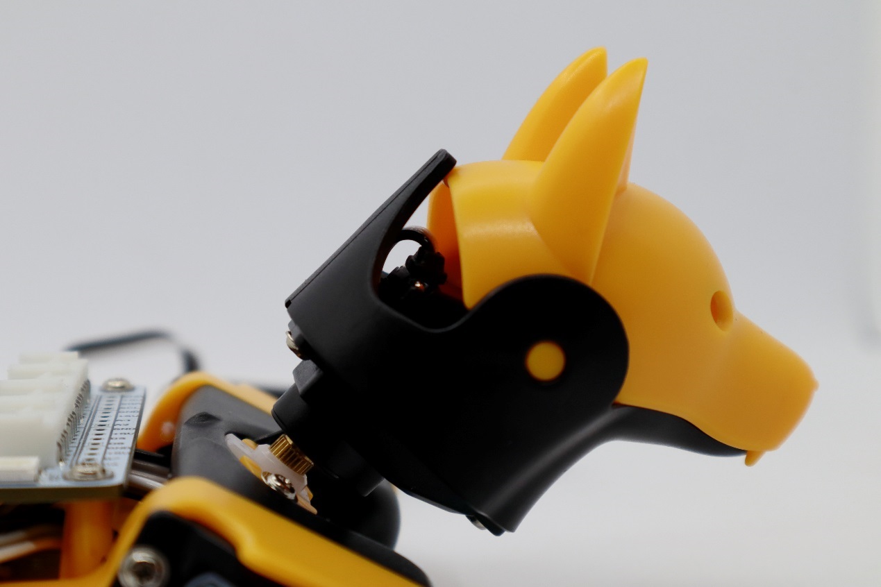
Install the neck servo
In the calibration mode, place the head as close to the central axis as possible and insert its servo shaft into the neck's servo arm.
Press down on the head so it is firmly attached to the neck.
Install the legs
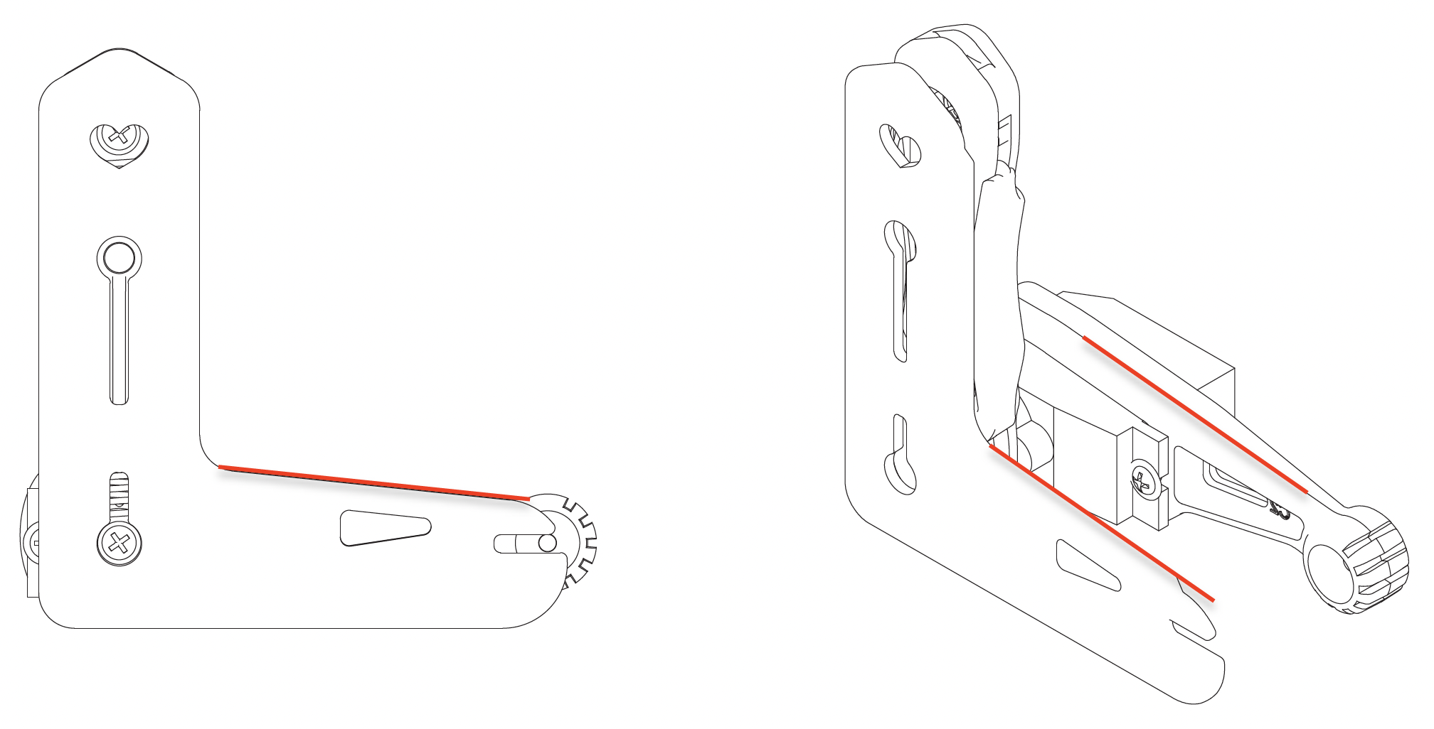
Install the upper leg and lower leg components to the output teeth of the servos when the Bittle is powered on and in the calibration mode. Please keep the torso, upper leg, and lower leg installed vertically as much as possible. Pay attention not to install the lower leg backward (the correct orientation is shown in the picture below).
Use the included L-shaped tool as a reference
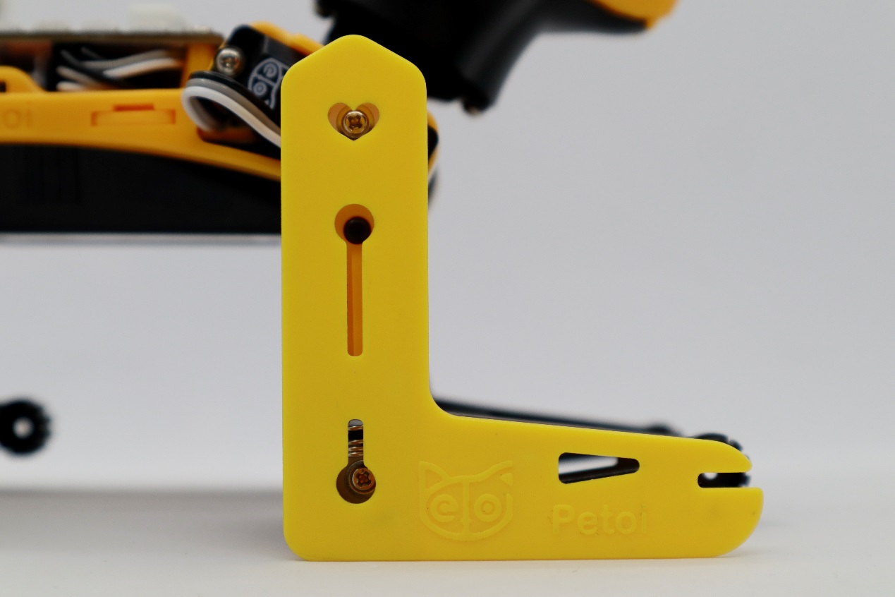
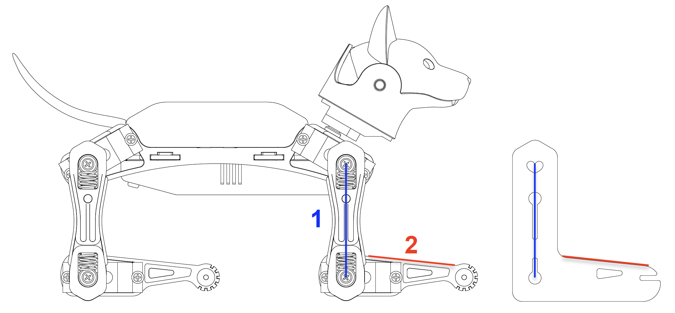

First, select the index number of the joint servo from the diagram(when adjusting the leg servo, adjust the thigh first, and then adjust the calf).
Then, click the "+" or "-" button to fine-tune the joint to the desired angle.
If the offset is more than ±9 degrees, you need to remove the corresponding part of the servo, reinstall it by rotating one tooth, and then press the "+" or "-" button.
For example, if you need to use -10 as the calibration value, remove the limb, rotate it by one tooth, and then reattach it. The new calibration value should be around 4, i.e., they sum up to 14. Avoid rotating the servo shaft during this adjustment.
Test the calibration effect
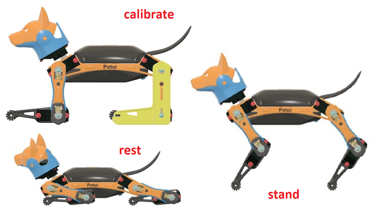
You can click the skill buttons to switch between Rest, Stand, and Walk to test the calibration effect.
If you want to continue calibrating, please click the Calibration button, and the robot will return to the calibration mode, with all servos immediately moving to their calibration positions.
Note:
You may need a second round of calibrations to achieve optimal results.
After calibration, remember to click the Save button to save the calibration offset. Otherwise, click "<" in the upper left corner to abandon the calibration.
Install the screws for the construction kit
For the construction kit, after completing the joint calibration, install the center screws to fix the leg parts and neck servo gears.
Last updated